Summary
Generative design is an approach in which the engineer does not draw the part but sets the conditions, and the software finds the shape. You define the space the part may occupy, the supports, the loads, the material and the manufacturing process. The software then removes material that carries no load and offers several variants.
Topology optimization is the older term, generative design the newer one. There used to be a difference, but today's generative design tools are built on topology optimization algorithms. That is why, in practice, I treat them as one.
It makes the most sense for parts where mass is critical and the load is clearly defined, typically in aerospace and automotive. It makes no sense for parts whose shape is dictated by a function unrelated to load bearing, or when producing an organic geometry costs more than the mass it saves.
Why there are two terms for the same thing
Topology optimization has existed as a concept much longer than generative design. The 1988 paper by Bendsøe and Kikuchi is usually cited as the foundation of the modern field. Generative design as a market term became visible only in the middle of the last decade, when software vendors started offering it as a separate tool.
The difference was once real. Topology optimization started from an existing, given geometry and looked inside it for material that could be removed. Generative design started from zero, purely from conditions and space boundaries, and produced several solutions instead of one.
In practice that difference has almost disappeared. Tools sold as generative design use topology optimization algorithms as their core mathematical mechanism, simply extended with additional input parameters. In my view, topology optimization has effectively converged into generative design. That is why I use the two terms as one in this article.
| Topology optimization, classic | Generative design, classic | |
|---|---|---|
| Starting point | Existing geometry | Only conditions and space boundaries |
| Number of solutions | One optimal solution | A range of variants with different tradeoffs |
| Manufacturing process | Often considered afterwards | Set as an input parameter |
| Mathematical basis | Topology optimization algorithms | Same algorithms, extended with more parameters |
| In practice today | Practically the same | Practically the same |
What the software actually does
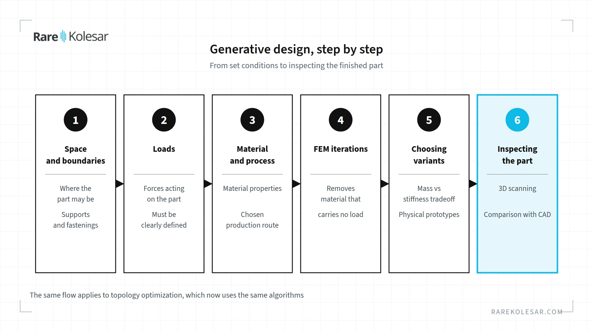
Generative design does not start from a drawing but from conditions. The engineer defines:
- the space the part is allowed to occupy,
- the points where the part is supported or fastened,
- the loads acting on it,
- the mechanical properties of the material,
- the manufacturing process that will produce the part.
The software then uses the finite element method, known as FEM. This is a calculation that divides the part into a large number of small elements and computes the stress in each one. Based on that, the software iteratively removes material from areas that do not contribute to load bearing. The process repeats until what remains is a geometry that carries the given load with minimum mass, within the limits of the chosen process.
The result is not one solution but usually a whole range of variants. Each represents a different tradeoff between mass, stiffness and manufacturability. The engineer then picks the few designs that make the most sense for the team. With additive manufacturing, each can quickly be built as a physical prototype and tested, instead of choosing on simulation alone.
Why the result looks unusual
To an engineer used to standard profiles, tubes and ribs, the first encounter with generative design often feels strange. The geometry as a rule looks like bone or a grapevine, without a single straight line and without a constant cross section.
That is not a flaw, quite the opposite. The resemblance to organic shapes confirms that the shape is good. Bone and grapevine are among the best examples in nature when it comes to the ratio of mass to load bearing capacity. When the software arrives at a similar shape on its own, it is a sign that the solution is structurally efficient, not that something went wrong.
This is why such geometry cannot be designed by hand in reasonable time. Nor is it easy to draw with classic CAD tools based on extrusion, revolve and Boolean operations.
The link with additive manufacturing
Generative design is almost always associated with additive manufacturing. The reason is simple, additive manufacturing is the only process that can produce fully free, organic geometry without compromise.
It is fair to say that current tools can also target other processes, for example 2.5, 3 or 5 axis milling, casting or cutting. The software then constrains the shape so that a tool can reach it or the part can be pulled out of a mold. The result is a lighter part, but far less organic. The full potential of the approach still only shows when the process is additive.
Modern tools take the chosen manufacturing process seriously in the analysis itself. They do not assume a generic material detached from the reality of printing, but include the parameters of the specific technology and material. I have personally worked with several such tools, and today this is the standard, not the exception.
Some solutions even make it possible to integrate the needed support into the shape of the part. The software then limits the overhang angle so the part supports itself, or designs the support as an integral part of the geometry. Support removal and part of the post processing simply fall away.
Once the part is printed, the geometry usually has to be checked by 3D scanning. Classic tactile measuring equipment measures individual points and struggles to describe such organic surfaces. I wrote about this in more detail in the article on reverse engineering and 3D scanning. The kinds of software that cover these steps are described in the article on software that makes a difference in additive manufacturing.
Two well known examples
In 2015, Airbus and its partners presented an A320 cabin partition designed with generative design and printed from an aluminium, magnesium and scandium alloy. According to the announcement, the partition was 45 percent lighter than the existing one, about 30 kg less.
In 2018, General Motors showed a seat bracket in which eight parts were merged into one. The new part was 40 percent lighter and 20 percent stronger. It was a demonstration part, not series production, but it shows well how generative design naturally combines with assembly consolidation.
When generative design makes sense and when it does not
Generative design makes the most sense for parts where mass is critical and the load is clearly defined. Typical examples are aerospace and automotive.
It makes no sense to apply it to parts whose geometry is already dictated by a function unrelated to load bearing, for example housings that primarily protect electronics. It also makes no sense when producing the organic geometry costs more than the mass saving it brings.
| Makes sense | Does not make sense |
|---|---|
| Mass is critical | Mass does not matter for the function |
| Load is clearly defined | Load is unknown or negligible |
| Part is made additively | Shape is dictated by function, for example an electronics housing |
| Mass saving pays back in service | Producing the organic geometry costs more than the saving |
If you are not sure which column your part belongs in, the free SLM DfAM Checker can serve as a first check for metal printing. For a concrete assessment at production level there is the production analysis.
Frequently asked questions
Are generative design and topology optimization the same thing? In practice today, almost. Generative design tools use topology optimization algorithms as their core mechanism, just with more input parameters and more variants on offer.
What does the engineer have to define before running generative design? The space the part may occupy, the supports or fastening points, the loads, the mechanical properties of the material and the manufacturing process. Without clearly defined loads, the result has no real value.
Why do generatively designed parts look like bones? Because the software leaves material only where it carries load. Bone and grapevine developed in nature on a similar principle, so a similar shape shows that the solution is structurally efficient.
Can generative design also be used for milling or casting? Yes. Current tools support milling, casting and cutting as target processes. The shape is then constrained and less organic, so the mass saving is usually smaller than with additive manufacturing.
How is a generatively designed part inspected? Most often by 3D scanning, because tactile measuring equipment struggles to describe free organic surfaces. The scanned shape is compared with the CAD model to reveal deviations.
For which parts does generative design make no sense? For parts whose shape is dictated by a function unrelated to load bearing, such as electronics housings, and for parts where producing the organic geometry costs more than the mass it saves.
Sources
- Topology optimization of multi-scale structures: a review, Structural and Multidisciplinary Optimization (Springer), 2021
- A topology optimization approach to structure design with self-supporting constraints in additive manufacturing, Journal of Computational Design and Engineering, 2022
- Manufacturing methods in the Generative Design workspace, Autodesk Fusion documentation, current version 2026
- Beyond additive manufacturing, generative design shapes for milling too, Engineering.com, 2020
- Autodesk and Airbus pioneering generatively designed 3D printed partition, Autodesk News, 2015
- GM seat bracket made with Autodesk generative design software, CompositesWorld, 2018