- A part designed for milling or casting rarely uses what 3D printing can actually do. The biggest gain comes when the shape is derived from the part's operating conditions, not from its existing shape.
- On five typical industrial tasks, the calculation produced an engine bracket 71 percent lighter, a manifold made of one part instead of three, a gripper finger 82 percent lighter and two molds with a 22 percent shorter cycle.
- These are demonstration calculations, not client parts. An independent verification calculation is in progress, and quantities and prices in the examples are assumptions.
The starting point is the operating conditions, not the existing shape
In the usual move to 3D printing, the part is taken as it is and simply printed. You pay for a more expensive technology and get nothing it has to offer. The other approach starts from what the part has to withstand: loads, pressures, temperatures, the points where it is attached and the space it has to fit into. From those conditions the calculation derives the shape, the internal channels and the material.
In practice this gives four kinds of results:
- Lighter parts with the same load capacity. Material stays only where it carries load.
- Many parts into one. An assembly of a block, plugs and seals becomes a single part, with smooth channels instead of drilled ones.
- Polymer jigs and fixtures. Gripper fingers, clamping elements and templates are calculated for FDM printing, with the weaker bond between layers taken into account.
- Molds with channels that follow the shape. The water channel runs just below the surface, where a drill cannot reach.
The wider picture of these approaches is in Assembly consolidation and Generative design in practice. Here are the concrete numbers.
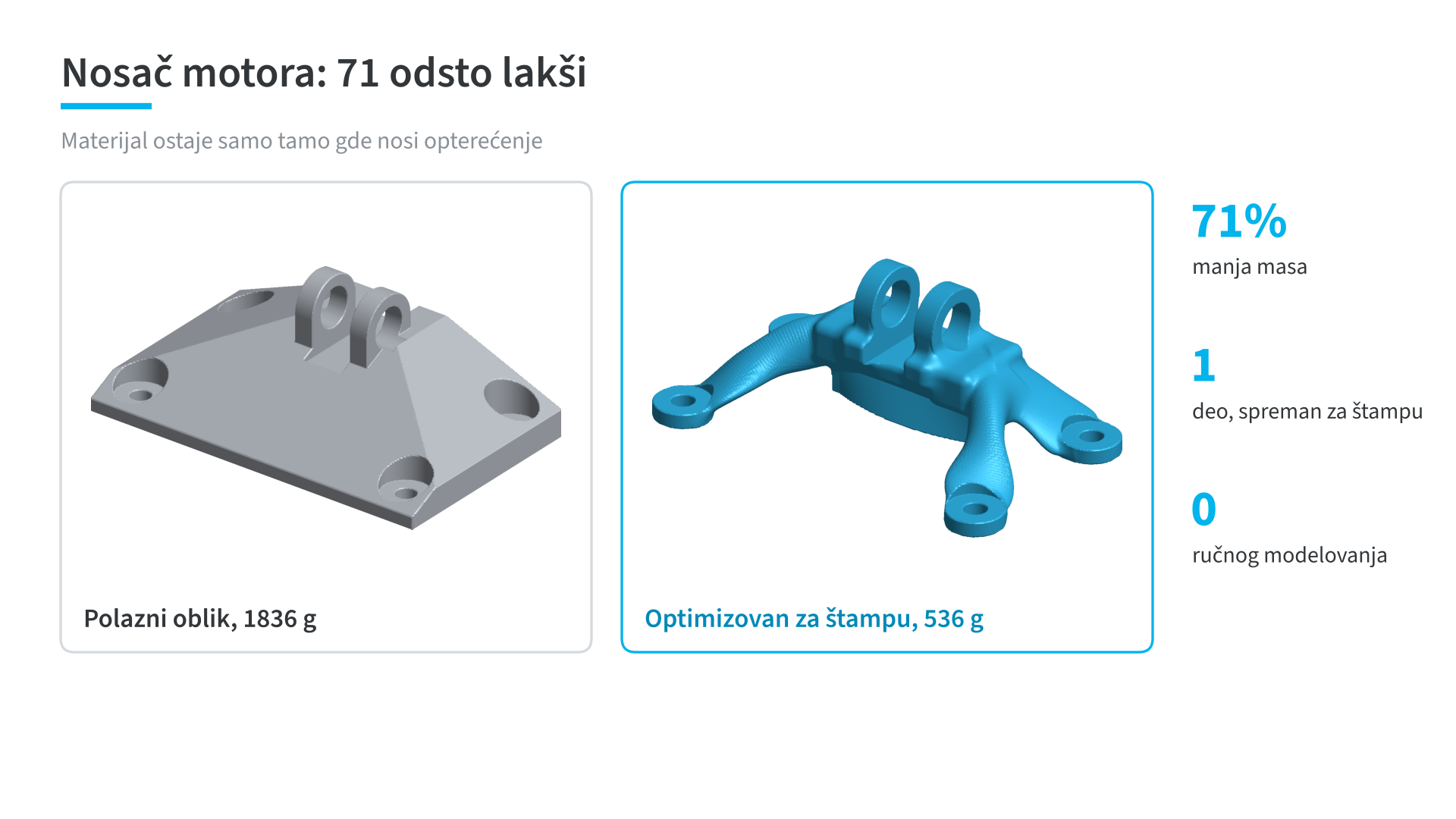
Engine bracket: material only where it carries load
The starting bracket weighs 1836 g. After optimization it weighs 536 g for the same operating conditions, 71 percent less. The shape comes from the calculation, without manual modeling, and is ready to print.
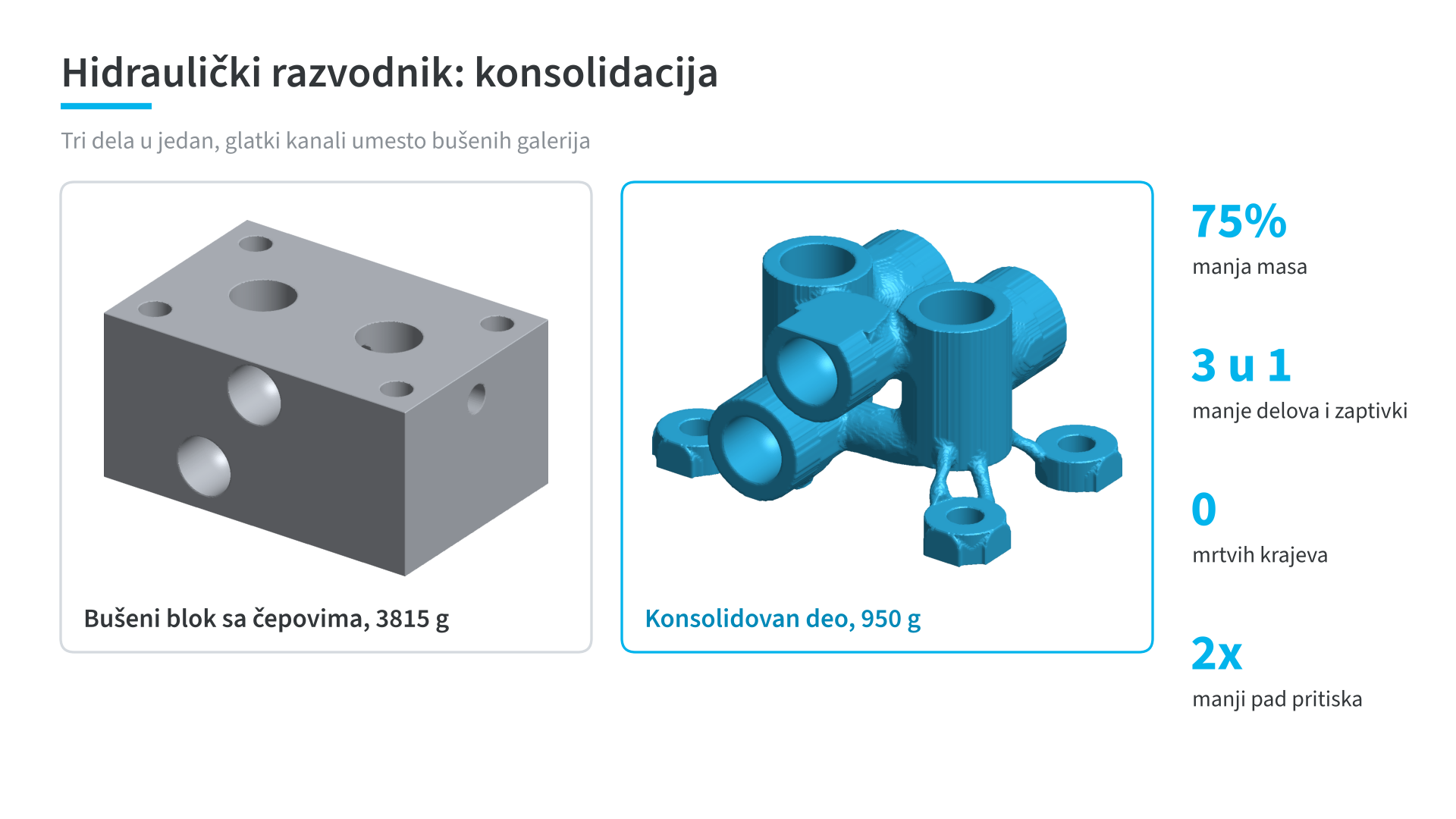
Hydraulic manifold: three parts into one
A drilled block with two plugs, 3815 g in total, is replaced by a single printed part of 950 g. One part instead of three, no dead ends in the channels, and half the pressure drop. The part is calculated for working and for proof pressure. Fewer parts mean fewer sealing points, less assembly and fewer places where something can leak.
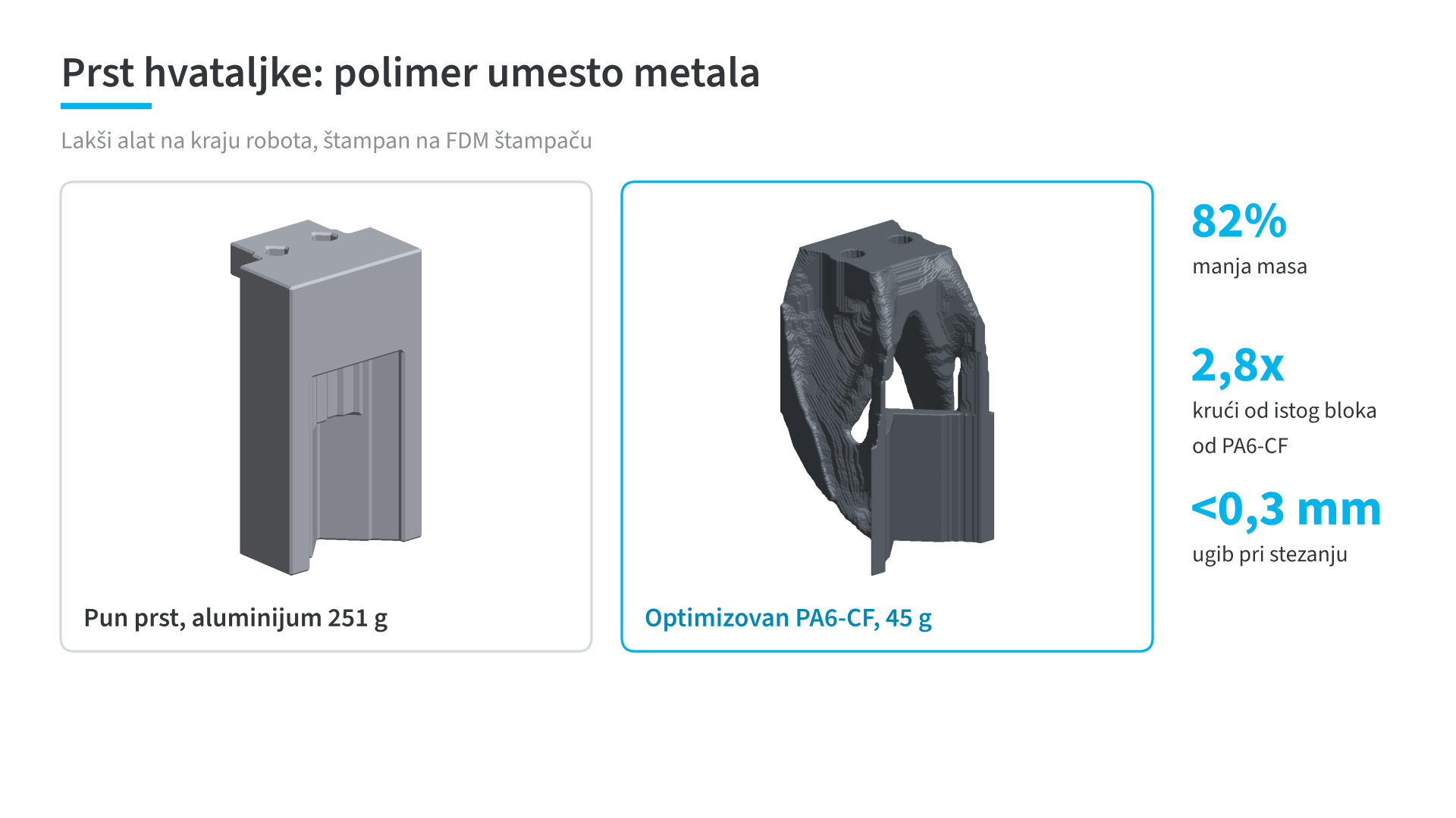
Gripper finger: polymer instead of aluminum
A solid aluminum finger weighs 251 g. The optimized PA6-CF finger, printed on an FDM printer, weighs 45 g, 82 percent less. Deflection under clamping stays below 0.3 mm, and the finger is 2.8 times stiffer than the same block of PA6-CF. A lighter end of arm tool puts less load on the robot, and a replacement finger is printed in a few hours.
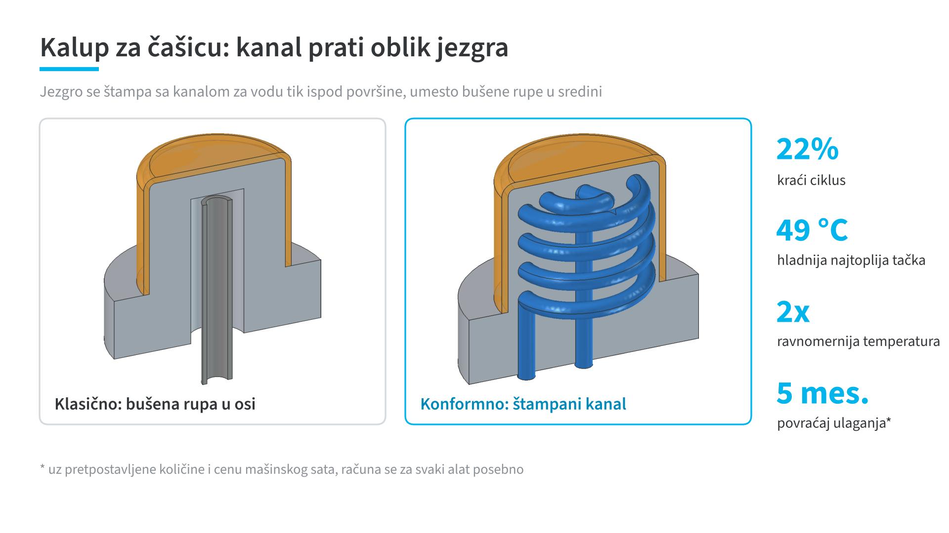
Mold for a cup: a channel that follows the shape
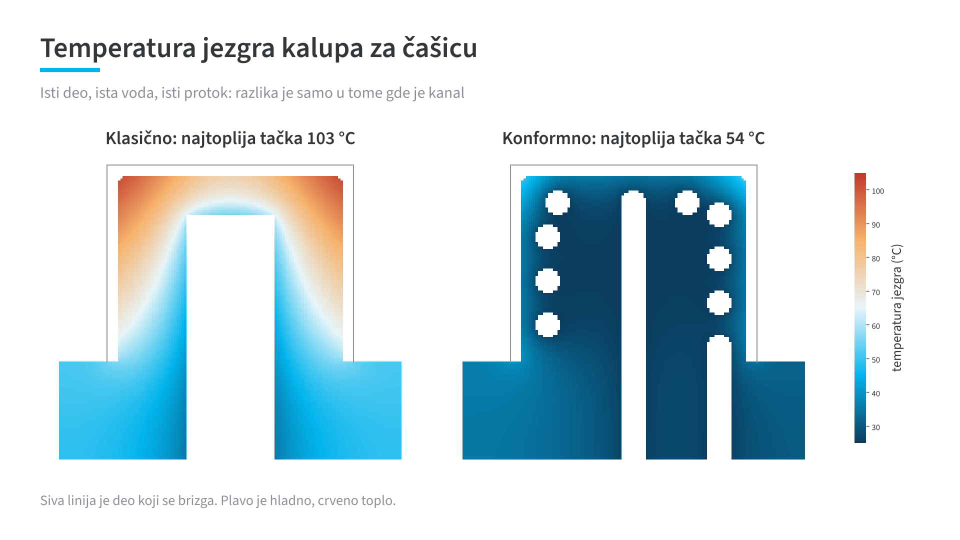
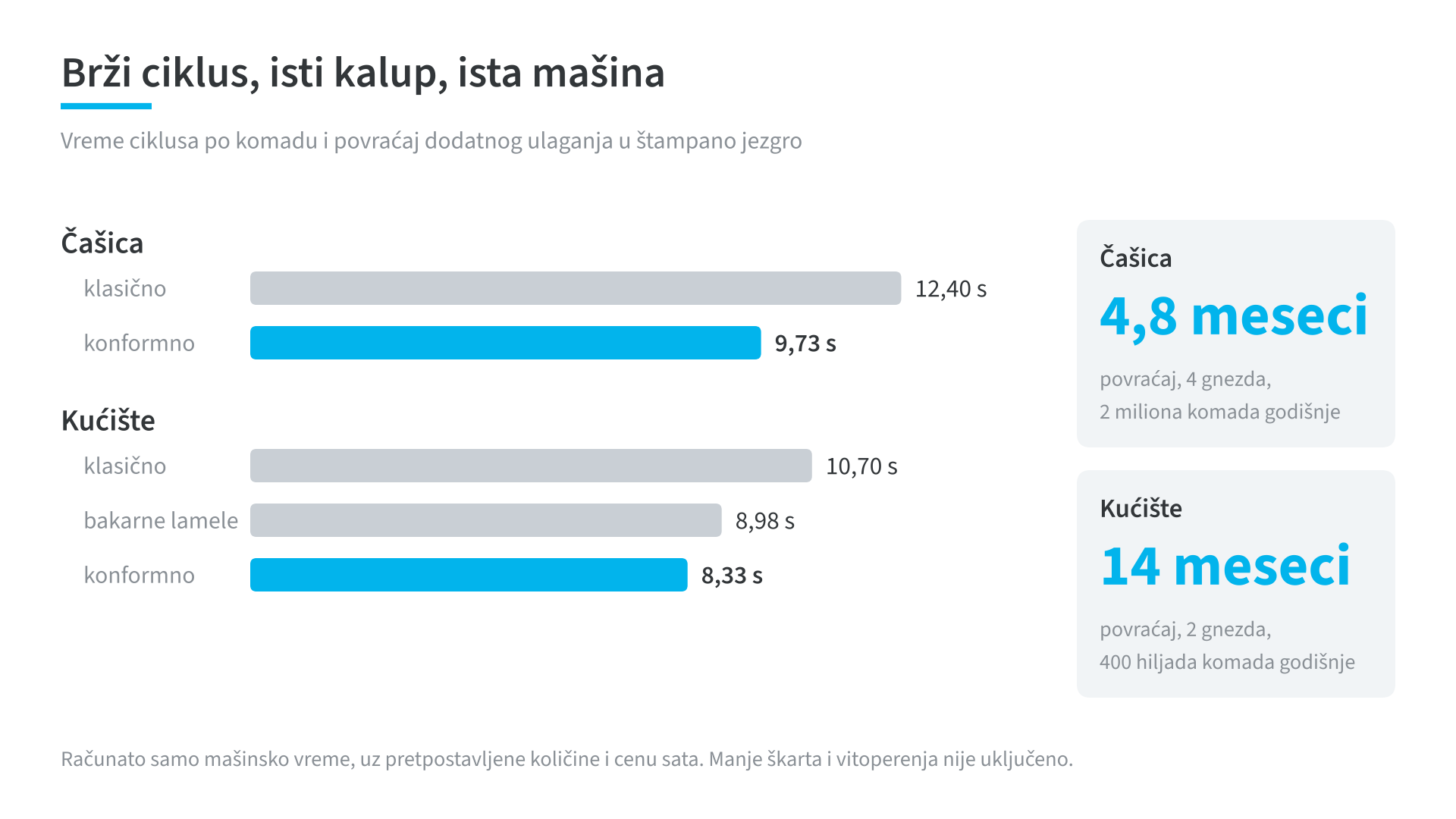
Instead of a drilled hole in the axis of the core, the printed core has a spiral channel just below the surface. The hottest point of the core is 49 °C cooler, and the cycle is 22 percent shorter, from 12.40 s to 9.73 s. With an assumed 2 million parts per year in a 4-cavity mold, the extra investment in the printed core pays back in about five months.
Mold for a housing with deep ribs
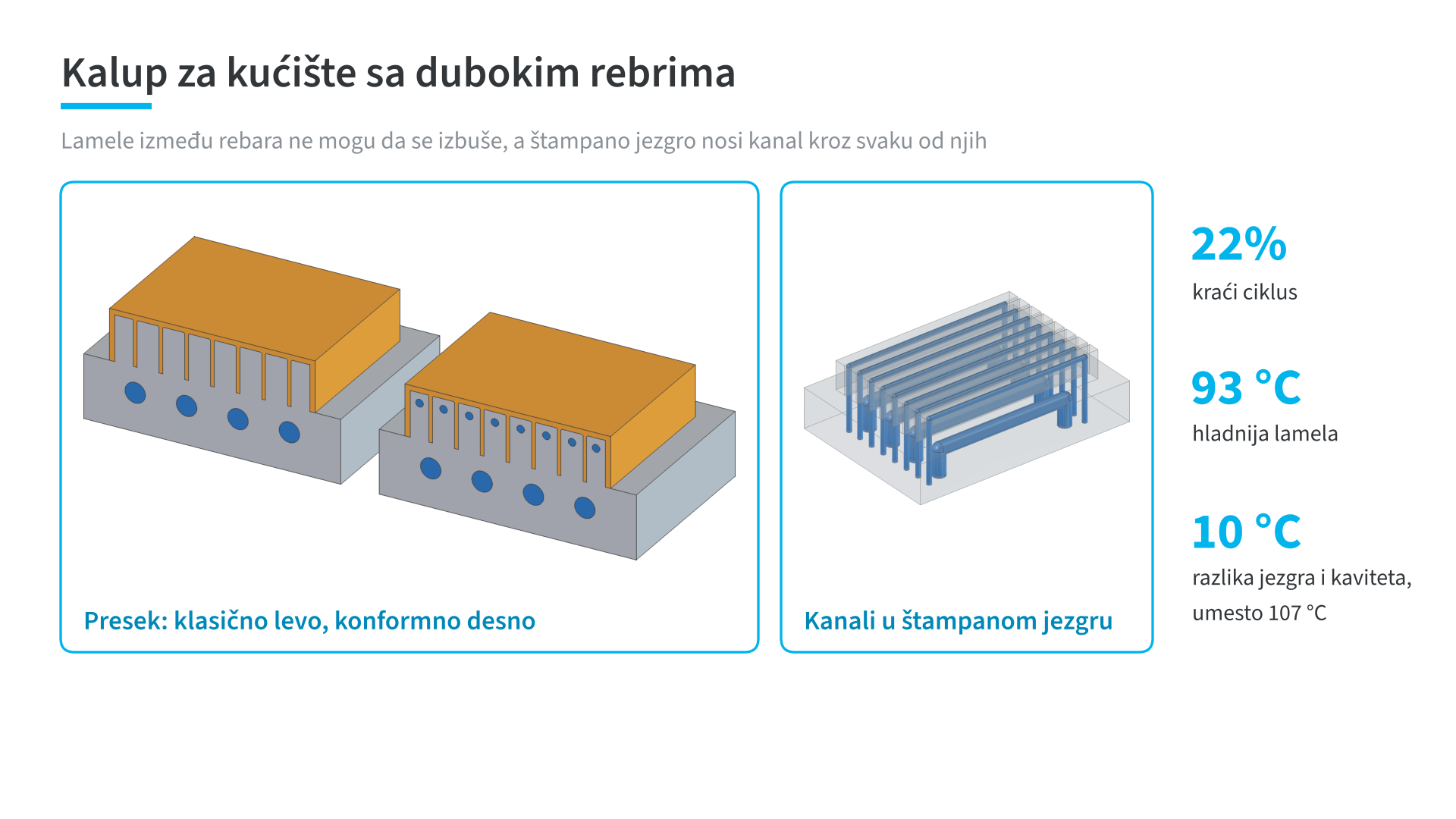
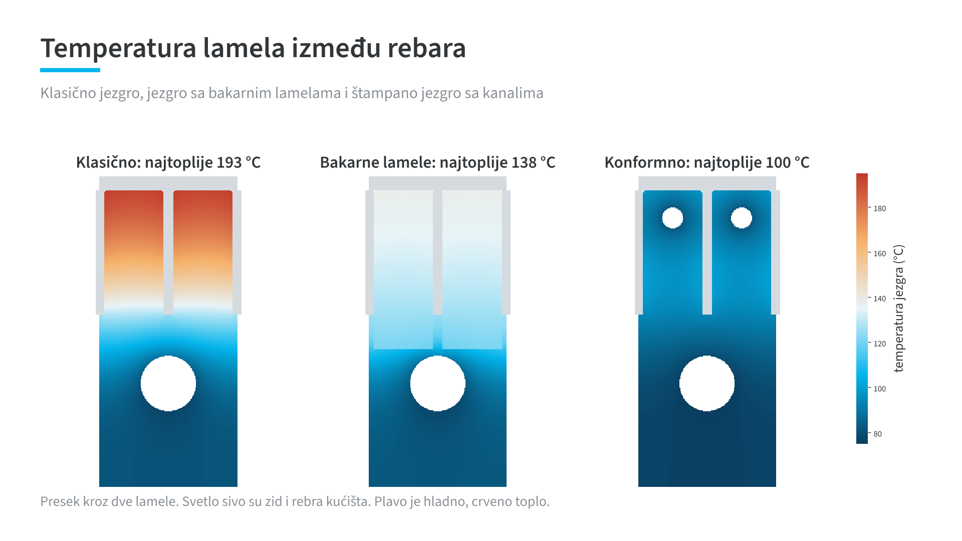
The steel blades between the ribs cannot be drilled conventionally, so they overheat to 193 °C. A printed core with a channel through every blade keeps them at 100 °C. The difference between the core and the outer mold half drops from 107 °C to 10 °C, and the cycle is 22 percent shorter, from 10.70 s to 8.33 s. We also compared a solution with copper blades. It helped, the blades are at 138 °C, but less than the printed core. With an assumed 400 thousand parts per year in a 2-cavity mold, the investment pays back in about 14 months.
What these examples mean, and what they do not
These are demonstration calculations on five typical parts, not client parts. An independent verification calculation is in progress, and I will update this text when it is done. Quantities and prices are assumptions, and the payback calculation counts machine time only. Less scrap and less warping are not included.
The main point the examples show is this: the gain does not come from printing the part, but from deriving the shape from the operating conditions. The same part, simply moved to 3D printing, is usually more expensive and no better.
Where to go next
If you have a part, assembly or mold you think could be better, start with a production analysis. I am preparing shape optimization as a Dokimion module. What Dokimion does today, and how it fits with consulting, is on a separate page.