Summary
Additive manufacturing is the third way of manufacturing. The first two are removing material (milling, turning, drilling) and forming material (casting, forging, pressing, injection molding). Additive manufacturing does not replace these two approaches. It adds a third path, building a part layer by layer from a 3D model.
The biggest mistake I see in companies is treating additive manufacturing as another route to the same, already existing design. A part designed for CNC machining or casting almost never works fully well when it is moved to 3D printing without changes. And if it does work without any changes, that is a sign the part probably should not be printed at all, because none of the advantages are used and the price will be higher.
That is why DfAM (Design for Additive Manufacturing) exists. It is an approach that starts from the capabilities and limits of the technology itself, not from habits formed through other manufacturing methods.
Three ways of manufacturing, side by side
The international standard ISO/ASTM 52900 defines additive manufacturing as joining materials to make parts from 3D model data, usually layer upon layer, as opposed to subtractive and formative methods. So the standard itself positions it as a third path, not as a replacement.
I do not like the term "conventional manufacturing" for the first two ways. Additive manufacturing is becoming conventional too, so it should not be presented as something exotic. The real question is not which method is more modern, but which one fits a specific part.
| Removing material | Forming material | Adding material (additive) | |
|---|---|---|---|
| Principle | Excess is cut away from a blank | Material is shaped in a mold or die | The part is built layer by layer from a 3D model |
| Typical processes | Milling, turning, drilling, grinding | Casting, forging, pressing, injection molding | Powder bed fusion, material extrusion, photopolymerization, DED |
| Dedicated tooling per part | Not needed, standard cutting tools are used | Mold or die required, often expensive | Not needed |
| Geometry | Limited by tool access | Limited by release from the mold | Internal channels and complex shapes are possible |
| Strongest at | Precise surfaces, tolerances | High volumes, low cost per piece | Low and medium volumes, complex geometry, consolidation |
The history of this third path, from the first patents to the expiry of key patents, is covered in the post a brief history of additive manufacturing. Here I focus on what that third path means for design.
Why DfAM is essential, not optional
Building layer by layer opens possibilities that are impossible or economically unjustified with the other two methods. If those possibilities are not used and the part is simply copied from a CAD file intended for machining, the client gets a more expensive part with none of the advantages. I wrote separately about when additive manufacturing makes sense and when it does not.
Before the design itself, it is useful to do a production analysis, so you know what is really required of the part before any decisions on geometry are made.
Three examples show what this is about.
Generative design
Generative design, based on FEM (finite element method) analysis and the real mechanical properties of the material, removes material where it does not contribute to load bearing. The result is a lighter part that performs as well as the original or better. Topology optimization and generative design are essentially the same idea, so I use one term. This matters most in aerospace and automotive, where every gram has a direct cost.
Assembly consolidation
In my experience, assembly consolidation is the main topic today. This is where the most money and time are saved. Several parts that used to be joined with bolts, welding or bonding are designed as a single part. Potential failure points disappear and assembly gets shorter. I cover this in more detail in the post on assembly consolidation.
BMW recognized this long ago. As early as 2018, BMW announced it had produced one million 3D printed parts in ten years, and the soft top mechanism bracket for the i8 Roadster was the first printed metal part in its series production. That bracket is 44% lighter than the bracket on the previous model and was designed to print without supports, more than 600 pieces in a single build.
A good recent example is foldable phones. In 2023 Honor introduced a hinge shaft cover in titanium alloy for the Magic V2, made by laser powder bed fusion (PBF-LB). In 2025 OPPO printed hinge parts in Grade 5 titanium for the Find N5. I would not say foldable phones could not exist without 3D printing, but it made such small and thin hinge parts possible in such high volumes, which would be very complicated with other processes.
Internal geometries and conformal channels
In tools for plastic injection molding and die casting, cooling channels made additively can follow the shape of the tool cavity. Drilled channels are limited to the straight path of the drill. That is why they are called conformal, because their shape conforms to, or copies, the geometry of the cavity. This difference directly affects how evenly and how fast the tool cools, and therefore the cycle time. In one 2023 study, a tool insert with conformal channels made by metal 3D printing shortened the injection molding cycle by 38% compared to conventional channels.
Five basic principles of DfAM
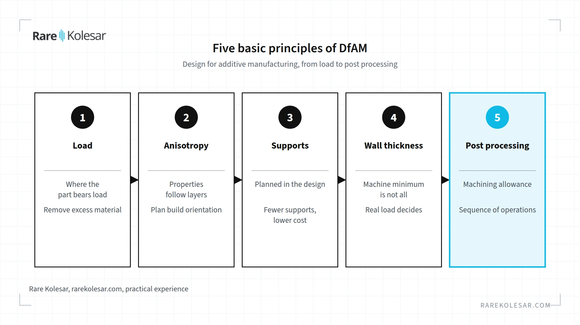
First principle, thinking in terms of load
You do not start from what is feasible with other methods. Instead of asking whether the part can be made, the right question is where the part really carries load and where material can be removed.
Second principle, awareness of anisotropy
Anisotropy means that material properties depend on direction. In most additive manufacturing processes, mechanical properties depend on layer orientation. A part that holds a load in one direction may fail in another. That is why build orientation is planned in advance, according to the real load in service.
Third principle, planning supports at the design stage
Supports, sometimes called support structures, are not a later correction but an integral part of the process. The part is designed to need as little support as possible on critical surfaces, because removing supports leaves marks and requires extra finishing. This is especially important in metal printing. Fewer supports make post processing much easier and directly reduce the cost of the part.
Fourth principle, wall thickness based on real load
There are two separate limits here. The first is the physical limit of the machine, the nozzle diameter or laser spot size, which sets the thinnest track the machine can deposit at all. The second, often more important, is that the thinnest printable track does not mean a functionally load bearing wall. A wall can be printable and still fail under its load in service. Thickness is therefore set by the real load, not only by what the machine can print.
Fifth principle, post processing and its sequence
If a part needs blasting, infiltration, heat treatment or machining after printing, the geometry must leave room for those operations. That includes machining allowance where material will be removed later. The sequence of operations matters just as much. For example, heat treatment after finish machining instead of before it can change the dimensions or properties of the part and undo the previous step.
How much post processing affects cost is shown by the Honor hinge. According to Metal AM magazine, the raw printed part costs about 4 dollars, while grinding and polishing add about 40 dollars more.
DfAM is not universal, it depends on the process
The rules for FDM printing with chopped carbon fiber filled filaments are not the same as the rules for SLS powder processes or for DED processes, where wire diameter, for example, is one of the basic constraints. Each technology has its own limits on overhang angle, minimum wall thickness, need for supports and available materials. An overview of the differences by technology is in the posts on technologies and processes.
Materials call for realistic expectations. In my estimate, there are several thousand qualified materials for additive manufacturing today. For engineering in general, Ashby states that 160,000 or more materials are available. Almost any material can be developed or adapted for additive manufacturing, but that is an expensive and long process that pays off only in special cases. For the vast majority of applications, the project has to fit what is currently available on the market. I explain how to approach this in the post on how to choose the right material without guesswork.
That is why serious DfAM is always done in the context of a specific machine and a specific material, not as an abstract set of rules. For metal parts made by laser powder bed fusion, you can run a first geometry check for free with the SLM DFAM Checker.
Frequently asked questions
What does it mean that additive manufacturing is the third way of manufacturing? Parts can be made by removing material (machining), forming material (casting, forging, injection molding) or adding material layer by layer. Additive manufacturing is that third path. It does not replace the first two, it complements them where it brings an advantage.
What is DfAM? DfAM (Design for Additive Manufacturing) is design for additive manufacturing. It is an approach that starts from the capabilities and limits of a specific printing technology, instead of rules inherited from machining or casting.
Can I print a part that was designed for CNC machining? Usually you can, but it rarely makes sense. Such a part is typically more expensive and uses none of the advantages of additive manufacturing. If the part works well without any changes, that is often a sign it should not be printed.
Why are cooling channels called conformal? Because their shape follows, or copies, the shape of the tool cavity. Drilled channels can only run in straight lines. Conformal channels cool the tool more evenly and shorten the cycle, by 38% in one 2023 study.
Why is build orientation so important? In most additive manufacturing processes, part properties depend on direction relative to the layers. A part can be strong in one direction and weaker in another. That is why orientation is chosen according to the real load already at the design stage.
Do the same DfAM rules apply to all technologies? No. Overhang angle, minimum wall thickness, need for supports and available materials differ between FDM, SLS, DED and metal powder bed fusion. DfAM is always done for a specific machine and a specific material.
Sources
- What is Additive Manufacturing, Wohlers Associates
- ISO/ASTM 52900, the 3D printing vocabulary standard, 3D MAG
- BMW marks milestone with millionth 3D printed part in ten years, VoxelMatters, 2018
- BMW Impresses with 3D Printed Roof Bracket for BMW i8 Roadster, 3DPrint.com, 2018
- Additively manufactured titanium hinge in Honor Magic V2 foldable phone, Metal AM, 2023
- OPPO's 3D printed smartphone hinge is pushing the limits of foldable design, TCT Magazine, 2025
- Efficiency Research of Conformal Channel Geometries Produced by Additive Manufacturing in Plastic Injection Mold Cores, Çalışkan et al., 3D Printing and Additive Manufacturing, 2023
- Materials Selection in Mechanical Design, chapter 1, M. F. Ashby, Elsevier, 2011