FDM 2.0, a robotic cell with variable material output
Summary
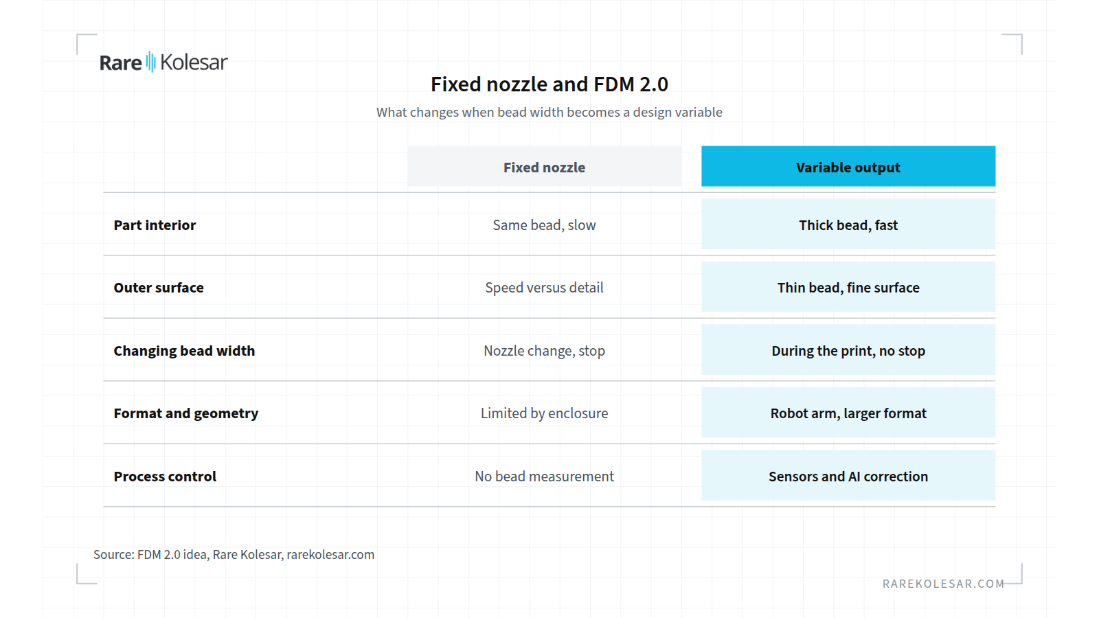
FDM 2.0 is my idea for solving the oldest limitation of FDM technology. Today one nozzle sets the bead width for the whole part. A thin bead gives a fine surface, but printing is slow. A thick bead is fast, but the surface is rough. I propose a robotic cell that changes the amount of molten material during the print, without changing the nozzle and without stopping the process.
In practice this means the inside of a part is built fast with a thick bead, while the outer surfaces are built precisely with a thin bead. A robot arm instead of a classic enclosed machine opens up larger formats and non standard geometries. Sensors and artificial intelligence monitor the process and correct deviations while the part is being built.
I have worked on this since 2023 through our joint project with the Faculty of Mechanical Engineering in Niš. The project reached the final pitch round at the Innovation Fund of Serbia in June 2024 and had a letter of support from Aibuild, a London based maker of robotic printing software. The idea is still open and I am looking for partners.
The main idea
Classic FDM works with a fixed nozzle. If you want both speed and quality, you choose a compromise or change the nozzle, which means a stop, new settings and a risk to the part. For large parts this compromise is the most expensive one, because hours and kilograms of material go into an interior nobody sees.
My proposal is a system that changes the amount of molten material during the print, without changing the nozzle and without stopping the process. Bead width is then no longer a property of the machine. It becomes a design variable, like wall thickness or infill density. The same part can have thick load bearing sections, thin details and a fine outer surface, in one continuous process.
Key system components
Variable material output. Instead of a fixed nozzle, material output changes dynamically. Internal structures are built fast, outer surfaces precisely. I expect less time and energy per kilogram of part and less post processing.
Robotic cell. A robot arm instead of a classic enclosed machine. This brings a larger build volume, printing at an angle and non standard geometries. The same cell can later get a milling tool, so the part comes out with machined functional surfaces.
Artificial intelligence and sensors. The system measures bead width and height, temperature and flow, compares them with the plan and corrects parameters during the print. Here AI has a clear role: fast correction based on measurement, not a replacement for engineering decisions. I wrote about where AI really helps in the post AI in 3D printing, where it really helps and where it does not.
Who has this problem
Anyone who prints large or thick parts by material extrusion.
- Makers of molds, patterns and tooling. Large molds and casting patterns need fast build up of mass and an accurate surface.
- Contract manufacturing of large parts. One failed print of a large part means a lost machine day and tens or hundreds of kilograms of material.
- The plastics processing industry. Companies that today mill tools and prototypes from solid blocks.
- Architecture, design and construction. Large format panels, formwork and elements, where the same logic applies to concrete and clay.
- Researchers and universities. Anyone designing structures where bead width is part of the design, not a consequence of the machine.
If you are not sure extrusion is the right choice for your part at all, start with the post how to choose the technology.
How the system would work, step by step
- Model analysis. The software splits the part into zones. Outer surface, thin details, load bearing interior.
- A toolpath with bead width per point. Each point of the toolpath also carries the target bead width, not only position and speed. Advanced robotic printing software can already describe bead width and height for every point.
- Robot and extruder with variable output. The robot arm guides the head, and the head changes material output according to the plan, without stopping.
- In process measurement. A camera or laser sensor measures the actual bead width and height, together with temperature and flow.
- Correction. An AI model compares measured with planned values and corrects flow, speed or the orifice before the error carries into the next layer.
- Process record. Every part gets a record of parameters and deviations. This is the basis for repeatability and for process qualification.
Work on the idea so far
The idea did not stay on paper. Since 2023 I have developed it through our joint project with the Faculty of Mechanical Engineering in Niš, under the working name extruder with variable nozzle diameter.
- Innovation Fund of Serbia. The project was submitted to the Fund and reached the final pitch round in June 2024.
- Industrial support. Aibuild from London, which develops software for large format robotic printing, gave us a letter of support. Their software can already write bead width for every toolpath point, which is the software half of this idea.
- Enterprise Europe Network. Since December 2024 the Faculty of Mechanical Engineering in Niš has had a public profile of our project on the Enterprise Europe Network. The profile describes a nozzle whose diameter and shape change during printing, in a range from 1 to 20 mm. The estimate stated in the profile is that printing of large objects could be up to 40 times faster. That is an estimate, not a measured result, and it is exactly what a pilot should test.
What already exists in the world
We are not the only ones on this path. In recent years other groups have also shown that a variable nozzle orifice is feasible. As far as I know, nobody has yet combined all three components in one industrial cell.
| Who | Year | Principle | Range and result | Status |
|---|---|---|---|---|
| Johns Hopkins University (Kang and Mueller) | 2024 | Eight movable pins joined by an elastic membrane | Changes orifice size and shape, smoother sloped and curved surfaces | Research, Science Advances |
| VSB Technical University of Ostrava, with partners from Norway and Finland | 2025 | Silicone sleeve compressed by a linear actuator | Orifice from 0.6 to 1.4 mm, wall thickness within 4 % of target | Research, hysteresis and a 15 to 20 s delay observed |
| Aibuild, robotic printing software | 2024 | Bead width and height for every toolpath point, linked to real time monitoring | The software side of variable output | Commercial software |
| Caracol, CEAD | current | Robotic cells for large format pellet and composite printing | Proof that robotic extrusion cells work in industry | Commercial systems |
I read two things from this table. First, the variable orifice mechanism has been shown, but in a small range or with limitations still to be solved, such as hysteresis and slow response. Second, the software and the robotic cells already exist. What is missing is the combination: a variable output head working with the software and with closed loop measurement, at industrial scale.
Older research showed that bead width can be changed even without a special nozzle, through flow rate, speed and layer height. Flow rate is the most effective lever. This is useful, but it works in a narrow range. For a wide range, from a fine surface to fast infill, a variable orifice is needed.
The link with toolpath design software
Variable output only makes sense if the software knows what to ask for. A classic slicer thinks in a fixed bead width. That is why I am interested in tools that write G-code directly and treat the toolpath as design.
One such example is WEFT, open source software from the Faculty of Construction Management at University Union Nikola Tesla in Belgrade. WEFT designs walls as a woven lattice, one continuous thread per layer, and checks the finished G-code before printing. Today bead width in WEFT is tied to the machine and the material. With variable output, the same wall could have thick load bearing rails and thin mesh threads between them. That is why I am talking with the WEFT authors about how these two directions could come together. I write more about the role of software in the post software that makes the difference in additive manufacturing.
What it takes to start
| Area | What is needed |
|---|---|
| People | A mechanical engineer for head design, a polymer and rheology specialist, a programmer for toolpaths and robot control, a machine vision and AI specialist |
| Equipment | A six axis industrial robot, a pellet or filament extruder that can take a variable orifice, a heated build platform, a camera or laser profile sensor |
| Software | Toolpath generation with bead width per point, robot control, in process data collection and analysis |
| Partners | A university for development and testing, a maker of robotic cells or extruders, a software partner, at least one industrial user with a real part |
| Funding | The Innovation Fund of Serbia, European research and innovation programmes, or an industrial partner funding development for its own application |
The most realistic first step is not the whole cell. It is a variable output head, tested on an existing robot or gantry machine, with one concrete part and a clear success metric, for example build time and surface quality compared with a fixed nozzle.
Why the concept stalled
The idea is technically feasible and had confirmation from an industrial partner, Aibuild. Still, it stalled, for reasons I still consider real.
- Long and expensive development. Head mechanics, control and software have to be developed together.
- A multidisciplinary team is needed. Mechanical engineering, polymers, robotics, software and AI are rarely in one place.
- Investors find disruptive technologies hard to accept. It is easier to fund an improvement of what exists than a change in how things are done.
- Implementation risk. A robotic cell with molten material needs safety, maintenance and training that small users find hard to carry.
My conclusion was that the idea was good, but the system was not ready for it at the time. Today I see more reasons to put it back on the table. Variable orifice research has appeared, software already works with bead width per point, and robotic cells have become a commercial product.
Risks and open questions
- Mechanism reliability. Moving parts in the zone of molten polymer suffer heat and wear. Research mentions hysteresis and slow response.
- Speed of change. If an orifice change takes seconds, the software has to plan it in advance, not only react.
- Fiber materials. Materials filled with chopped carbon fibers are abrasive. CFF, printing with continuous fiber, is a completely different process and this concept does not cover it.
- Qualification. Variable bead width changes mechanical properties by zone. Functional parts need testing by zone.
- Market. It has to be shown that the time and material saved outweigh the cost of a more complex head.
Frequently asked questions
What does variable material output mean in FDM printing? It means the amount of molten material and the bead width change during the print, with no nozzle change and no stop. The interior is built fast with a thick bead, and the surface finely with a thin bead.
How is FDM 2.0 different from printers with several nozzles or automatic nozzle change? With several nozzles or a nozzle change there is a stop and a jump between a few fixed sizes. FDM 2.0 changes output continuously, within the same toolpath, without stopping the process.
Why a robotic cell and not a classic printer? A robot arm gives a larger build volume, printing at an angle and the option for the same cell to mill later. For large parts, where the savings are biggest, a robot is the natural choice.
What role does artificial intelligence play in this system? AI compares measured bead width and height with the plan and corrects flow and speed during the print. Engineering decisions about the part and the material are still made by people.
Is there already a commercial system with a variable nozzle? As far as I know, there is no industrial cell that combines a variable orifice, software with bead width per point and closed loop measurement. There are research prototypes, and commercial software and robots that cover parts of that picture.
How can I get involved as a partner? I am looking for universities, equipment makers, software partners and industrial users with a real part for a pilot. Contact me through the consulting page, and we will see where your interest fits.
Let us talk
If you have a part that is slow or expensive to print today, or you develop extrusion equipment or software, I will be glad to talk. See also my idea for a center for reverse engineering and additive manufacturing, because such a center would be a natural home for this kind of cell. Contact details are on the consulting page.
Sources
- Innovative adjustable nozzle technology for high precision FDM 3D printing, Faculty of Mechanical Engineering in Niš profile, Enterprise Europe Network, 2024
- Variable Orifice Size Nozzle for 3D Printing, Journal of Manufacturing and Materials Processing (MDPI), 2025
- From Minecraft to Masterpieces: Adaptive Nozzle Enhances 3D Printing, Johns Hopkins University, 2024
- Variable bead width of material extrusion based additive manufacturing, Journal of Zhejiang University SCIENCE A, 2019
- Smart Toolpaths, Aibuild, 2024
- Robotic Advanced Manufacturing for large components, Caracol, 2026
- Large format additive manufacturing systems, CEAD, 2026
- WEFT, compiler for woven single thread walls, GitHub, 2026